Attack Graph Model Design Requirements and Examples
TL;DR OpenGraph makes it easy to add new nodes and edges into BloodHound, but doesn’t design your data model for you. This blog post has everything you need to get started with proper attack graph model design, including vocabulary, requirements, and examples.
Brief
For several years, one of the biggest pain-points with contributing to BloodHound has been in getting nodes and edges ingested and correctly displayed in the GUI. BloodHound OpenGraph changes that. Now it is easy for anyone to add nodes and edges into BloodHound through the easy-to-use /file-upload/ endpoint.
However, while the process of adding nodes and edge to the product is greatly simplified, the product will not function as expected without a well-designed attack graph model. This document seeks to educate users on attack graph model design theory, best-practices, and requirements.
An attack graph is a tool – a powerful force multiplier when wielded correctly, a frustrating and confusing hazard when not. This document aims to equip you with the knowledge and skills necessary to effectively wield this tool.
Basic Attack Graph Vocabulary and Design Theory
Graphs are well-understood, well-studied mathematical constructs. You can find thousands of guides, tools, and academic papers that make use of graphs. This document will not replace a proper education or time spent working with graphs. But in this section we will touch on the most fundamental aspects of a graph you must understand in order to effectively get BloodHound to work with your nodes and edges.
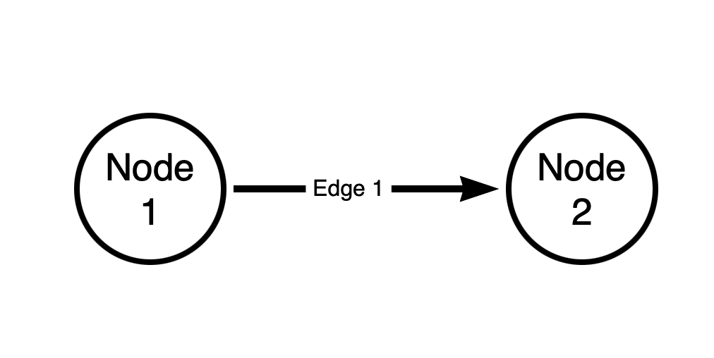
Every graph is constructed from two fundamental components: vertices (nodes) and edges (relationships):
Tool of the trade: All graph diagrams in this post are made with Neo4j’s Arrows application.
The above graph has two nodes and one edge. The edge is directed. The source node of the edge is “Node 1”. The destination node of the edge is “Node 2”.
Every edge in a BloodHound attack graph is directed, and is one-way. There are no bi-directional (“two-way”) edges in a BloodHound graph.
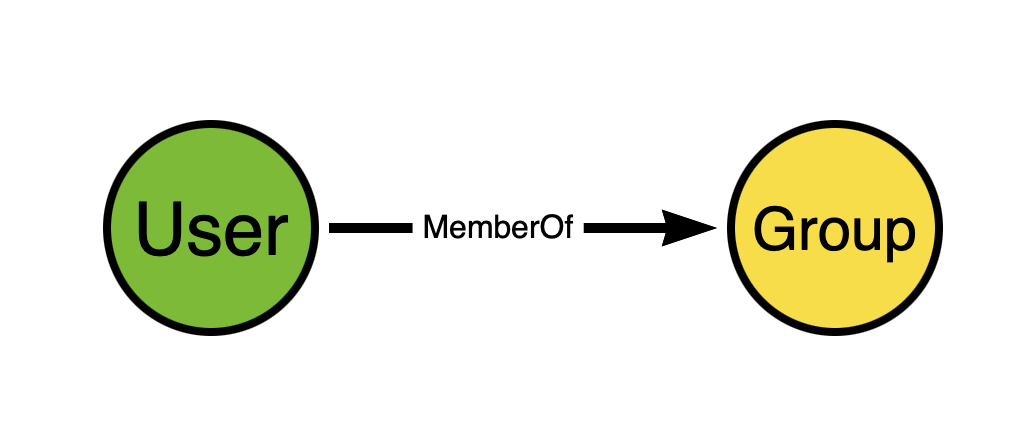
In a BloodHound attack graph, the direction of the edge must match the direction of access or attack. Let’s look at an example with Active Directory group memberships.
In the BloodHound attack graph, we model Active Directory security group memberships like this:
Think about the direction of the edge. Now think for a moment and try to figure out why we don’t model AD security group memberships like this instead:
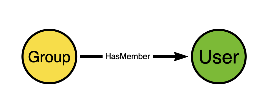
This seems perfectly reasonable at first glance, does it not? But remember that we are constructing an attack graph in order to discover attack paths. Edge directionality must serve attack path discovery.
The direction of the edge going from the group to the user does not expose any attack path. Just because a user is a member of a group does not mean the group has any “control” of the user. But when the direction of the edge is from the user to the group, that DOES serve attack path discovery.
Why? Because in Windows and Active Directory, members of security groups gain the privileges held by those groups. Let’s extend the model a bit to make this easier to see:
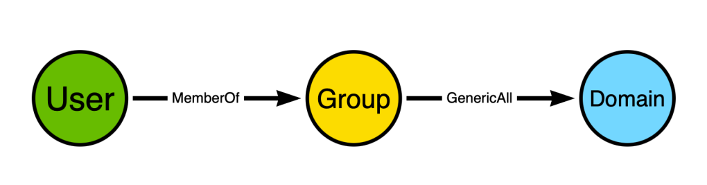
The user is a member of a group, and the group has full control of the domain. When the user authenticates to Active Directory, their Kerberos ticket will include the SID of the group. When the user uses that ticket to perform some action against the domain object, the security reference monitor will inspect the ticket, see the group SID, and grant the user all the permissions against the domain that the group has*.
*In reality the process is much more involved than this, but work with me here, people.
The above diagram shows a path connecting two non-adjacent nodes. Adjacent nodes are those that are connected together by an edge. In the above diagram, the adjacent nodes are:
- “User” and “Group” via the “MemberOf” edge
- “Group” and “Domain” via the “GenericAll” edge
The “User” and “Domain” nodes are non-adjacent, yet there is a path connecting the “User” node to the “Domain” node.
When designing your attack graph model, you must be aware of the patterns that will emerge from your design. There are many examples out there of people who want to make a contribution to the BloodHound graph who do not seem to be aware of this. Instead of proposing nodes/edges that create multi-node patterns, they propose nodes/edges that result only in one-to-one patterns:
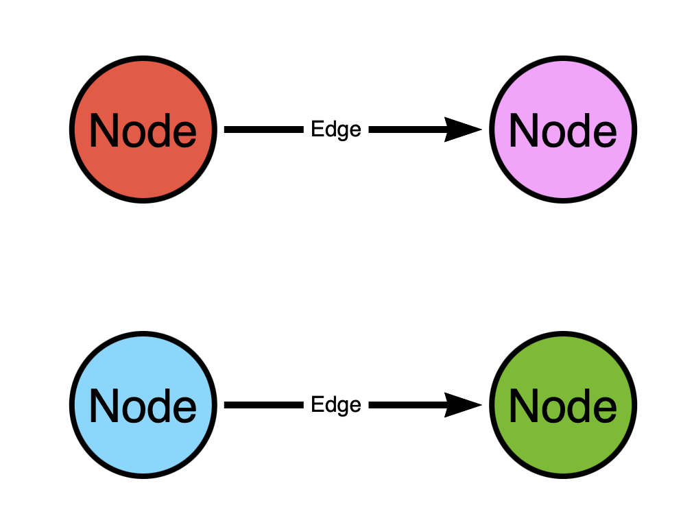
In the above graph there two paths:
- From the red (top left) to the pink (top right) node
- From the blue (bottom left) to the green (bottom right) node
What’s wrong with this design?
Think of the graph as a map of one-way streets. In the above graph we have two one-way streets. But this map kinda sucks, doesn’t it? You can only start in two places and you can only go to two places. You can’t go from the red (top left) node to the blue (bottom left) node because there is no path connecting those nodes.
This is a much better map:
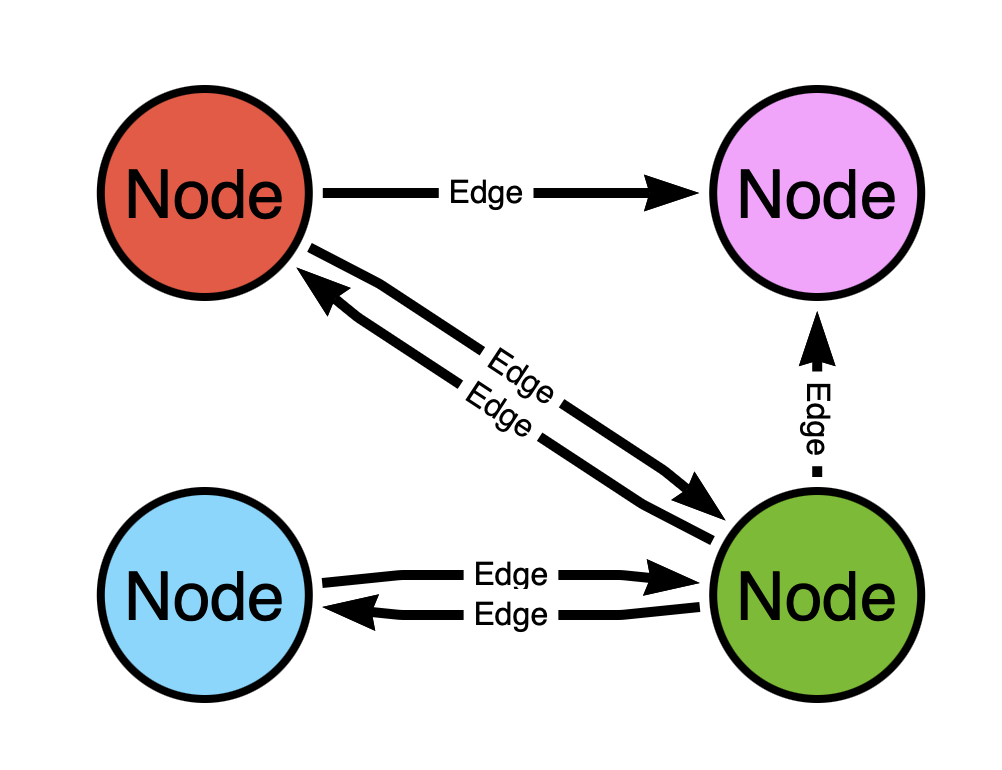
Now is there a path from the red (top left) node to the blue (bottom left) node? Yes! It goes through the green (bottom right) node!
The difference in the two graphs is the level of connectedness, or how well-linked the nodes are to one another.
Let’s belabor the point a little more to make it even more clear. The top model would be analogous to having a node represent both a person and the address where they live, with the edge representing the fact that they live at that address:
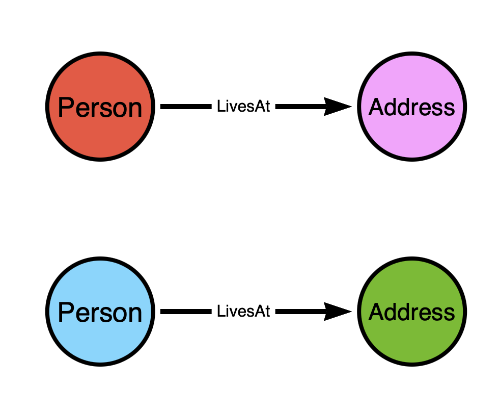
While the bottom graph would be analogous to having the nodes represent the addresses and the edges represent streets:

It should be obvious that for the sake of path finding, the second model is the only model that will work.
This is actually how Google Maps works under the hood – it is a graph where locations are nodes and streets are edges.
Let’s review with a simple quiz:
- What are the two fundamental components of a graph?
- All edges in a BloodHound attack graph are ________
- Two nodes connected by a single edge are said to be:
- Friends
- Paths
- Adjacent
- Justin said “do better” and I’m really starting to internalize that in a way that is starting to concern me
- Why does connectedness of the graph matter?
Quiz Answers
- Vertices (or nodes) and edges (or relationships)
- Directed
- Adjacent
- Because weakly connected graphs produce fewer paths
BloodHound Attack Graph Model Requirements
You don’t want to pour your heart and soul into a data model only to find out that most BloodHound features don’t work with your model. Here are the non-negotiable requirements your model must comply with to work with BloodHound:
Requirement 1: Universally Unique Node Identifiers
Every node in a BloodHound database must have a universally unique identifier to distinguish it from every other node. You must identify the source and format of that identifier.
We used to use UPN-formatted names for identifiers in BloodHound (e.g.: “DOMAIN ADMINS@CONTOSO.COM”). Surprise surprise, UPNs are not guaranteed to be universally unique. We now use SIDs instead for universally unique identifiers for most Active Directory principals.
One of the best universally unique identifiers is a GUID. Does the entity you are modelling have a GUID? If so, great! If not, you’re going to need to find something else.
Examples of bad identifiers:
- Usernames
- Email addresses
- Hostnames
- IDs that start at “0” and increment from there
Examples of good identifiers:
- GUIDs
- SIDs
- Certificate thumbprints
Think: how does the system itself differentiate between these objects? In many (but certainly not all) cases, you may do well to identify your nodes the same way the system uniquely identifies its objects.
Note 1: The “bad” identifier examples above will serve just fine as node “display names”. Universally unique identifiers must be unique – display names do not have the same requirement.
Note 2: The best object identifiers are static and predictable. Don’t create random GUIDs for your nodes.
Note 3: It’s best to choose identifiers that are easily read by low-privilege principals. You want to give your data collector “read only” or “audit” rights, not admin rights (if you can help it)
Requirement 2: Distinct Node and Edge Classes
If you are modeling a new system not currently modeled by BloodHound, your nodes and edges must have distinct classes that do not overlap with existing BloodHound node and edge classes.
Sorry, but “MemberOf” is already taken, so you will need to use a different edge class when modeling group memberships in Okta, Zoho, AWS, or whatever else.
Tip: Prepend your edge names with the platform you are modeling. For example, you could use an edge class of “AWS_MemberOf” to model AWS group memberships.
The complete list of BloodHound node and edge classes can be found here:
Requirement 3: Your Model Must Connect Non-Adjacent Nodes with Paths
If your graph model does not create paths connecting non-adjacent nodes, you should be using a relational database, not a graph database. You are using the wrong tool for the job!
Example Attack Graph Data Models
Your attack graph model must produce attack paths that are the result of the modeled system’s mechanics and configurations.
The two most significant mechanics of the system that will dictate your model include:
- How the system authenticates principals, and the artifacts created during authentication
- How the system authorizes actions
Your model will also be influenced by how configurations of the system can influence authentication and authorization. Let’s see some examples:
Example 1: Discretionary Access Control
Active Directory has at least a couple different authentication systems:
- Kerberos
- NTLM
Those authentication systems create different artifacts that have dictated the BloodHound model. Most notably are process tokens (aka primary tokens). When an AD user performs a console logon, the host will use process tokens to prove the user’s identity to other hosts in the network. An adversary with control of the host can steal/use those tokens to impersonate the user.
Those tokens are objects in the Windows operating system. But we’ve chosen not to model those tokens as nodes in BloodHound. Why?
Because the DACL of a token can only be read locally, and our data collection runs remotely.
And so we are faced with this question:
How do we model user impersonation via token re-use?
The answer is with this model:
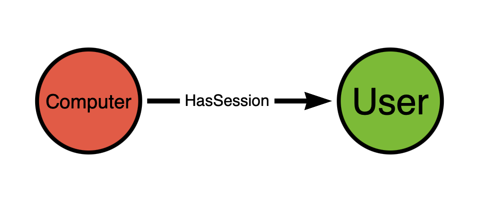
We know that an attacker with SYSTEM level rights on the host will be able to impersonate every logged-on user by stealing/re-using process tokens. And so we create the edge starting from the computer and ending at the user. There are probably a dozen components of the operating system involved in this abuse primitive, but we don’t need to include those in the model. What we have above suffices.
Now let’s talk about authorization. Windows and Active Directory use the following data sources when making authorization decisions:
- The DACL of the target securable object
- User Rights Assignments
The DACL contains ACEs that describe which principals are allowed to perform certain actions against that object. When you want to understand, for example, who has full control of a user, the answer is found by inspecting the user itself – specifically the user’s DACL.
For example, a group may have “full control” of a user. That is reflected as a “Generic All” “allow” type ACE on the user’s DACL. We model that in BloodHound like this:

Note that in this model, the ACE is modeled as an edge, not a node.
We did not create a node to represent the ACE nor the DACL. We did not create a node to represent the security reference monitor.
Why not? Because we are modeling the outcome of the authorization decision system, we are not modeling the system itself.
Example 2: The Very First BloodHound Model
This was the first BloodHound attack graph model:
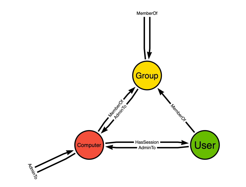
There are only three node classes and three edge classes. This simple graph design is one of the primary reasons BloodHound succeeded so well in its early years. Why? Because of the connectedness of the design creating paths.
From the simple design above came attack paths that stretched across domain trust boundaries, crossing multiple computers and users, and dramatically sped up our privilege escalation efforts.
Your model does not need to look complicated, but it does need to be as well-connected as possible.
Let’s pause here for a moment to talk about how to read the above graph design. There are three nodes in the above design:
- User
- Computer
- Group
These nodes represent classes, not atomic objects. The “User” node represents all “User” nodes in your database. The outbound “MemberOf” edge from the “User” node to the “Group” node means that a “User” node in the graph can have a “MemberOf” edge directed at a “Group” node.
This image is the design of the graph, not necessarily the graph itself. The “MemberOf” edge starting and ending at the same “Group” node means that an Active Directory security group can be a member of another AD security group.
Example 3: Role-Based Access Control
In the above example we looked at how we can model discretionary access control. Now let’s look at role-based access control.
RBAC works differently than discretionary access control (duh). In a discretionary access control system, permissions affecting an object are stored on that object itself. But in an RBAC system, permissions are stored on objects called “roles”, or “role definitions”.
A discretionary access control system makes authorization decisions based on a DACL stored on the target object.
An RBAC system makes authorization decisions based on the combination of permissions defined across all roles a principal currently has assigned to them. Those permissions are (typically) arranged by object class and authorized action.
RBAC systems also commonly include scopes in their role assignments, which define a set of objects that the role assignment is valid against. In this way, an RBAC role assignment forms a triple:
- The principal that has been granted the role assignment
- The scope of the role assignment
- The ID of the role the role assignment is associated with
Remember that we are modeling the outcomes of authorization system decisions. We are encoding into the graph a prediction of whether the system will allow or deny a certain action done by a principal when acting against another certain object.
Consider this scenario:
A user, “Bob”, has been granted the “Application Administrator” role in Entra. Entra uses an RBAC authorization system to make access decisions. When “Bob” goes to add a secret to a service principal, what information does Entra’s authorization system use to make an allow or deny decision?
Entra will inspect the token that was supplied in the request. It will decode the token and find the IDs of the Entra roles “Bob” has. It will then look up the roles by those IDs and look at the permissions in those roles. It will also inspect the role assignment “Bob” has for the role and read the scope of that role assignment.
In order to predict the outcome of this authorization decision, our data model must include the following elements:
- The principal, “Bob”
- The scopes of all “Bob”’s role assignments
- The hierarchical location of the target service principal
Because Entra built-in roles are immutable, and because Entra custom roles do not allow “abusable” permissions, we don’t actually need to model the permissions in the role definition.
The above three items may lead us to this model:
The problem with this model is that the overall pattern connecting the “User” to the “Service Principal” may not be valid – it might produce a false positive pattern. This is because while in our dreamt-up scenario “Bob” has “Application Admin”, we need a way to cover all built-in roles and not all built-in roles enable this particular kind of abuse.
This is where we introduce to you the concept of “traversable” and “non-traversable” edges.
Let’s go back to our Google maps analogy. Can you think of a type of road that, while it exists in real life, you would not want to or be able to drive on when trying to get somewhere?
What about these:
- Private roads
- Roads that are temporarily closed
- Roads that are for some reason impassable (e.g.: flooded)
- Dangerous or unmaintained roads
You still want those roads in your map, don’t you? But you don’t want to (or can’t) traverse those roads when going from point A to point B.
We have the same concept in BloodHound:
- Traversable edges will be included in path finding
- Non-traversable edges will not be included in path finding
This concept gives us great latitude in the graph model and lets us do something called post-processing.
Let’s go back to our example and explain how traversable edges, non-traversable edges, and post-processing come together to create an attack graph model that works.
Earlier we established we need three pieces of information to predict whether the Entra authorization system will allow or deny “Bob” when the user attempts to add a secret to a service principal:
- The principal, “Bob”
- The scopes of all “Bob”’s role assignments
- The hierarchical location of the target service principal
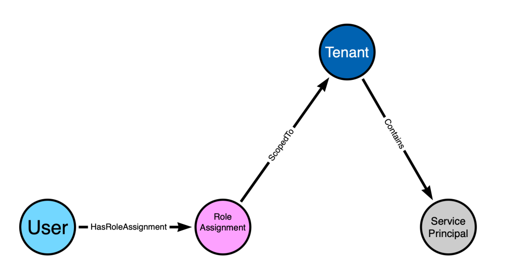
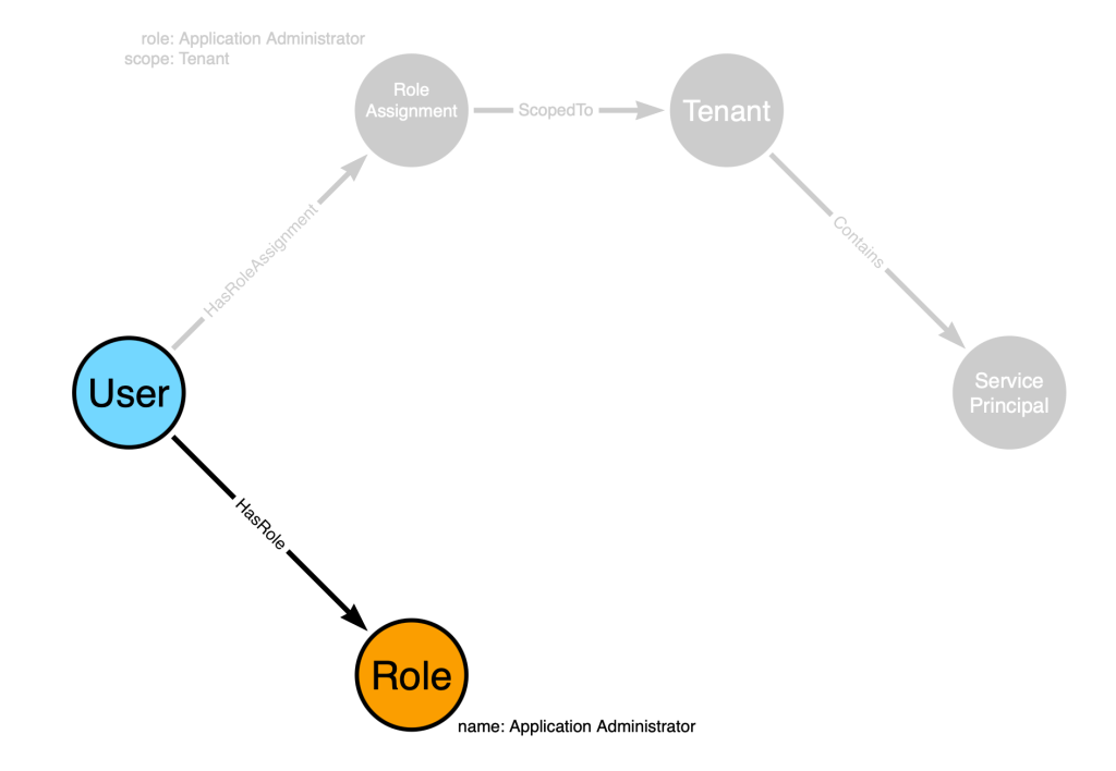
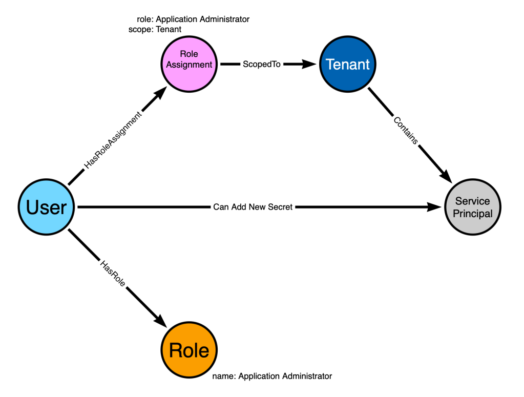
We will first model the system configurations like this:
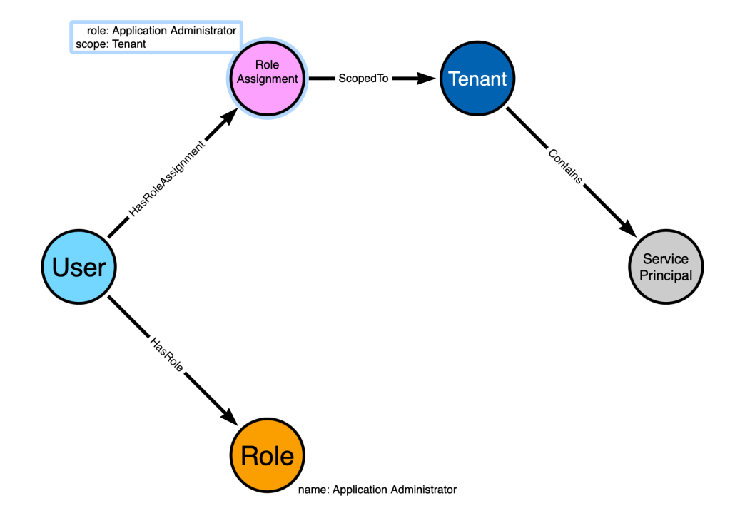
Let’s explain each node and edge:
- The “User” node represents our user, “Bob”
- The “Role Assignment” node represents a particular role assignment that has been granted to “Bob”. On that node we store the scope and role that the role assignment is associated it.
- The “Tenant” node represents the Entra tenant
- The “Service Principal” node represents an Entra service principal
- The “Role” node represents the Entra administrator role, “Application Administrator”
We can exercise this model to determine whether a valid path exists connecting the “Bob” node to the service principal node by simply following the existing directed edges starting at Bob and ending at the service principal. I’ll highlight those edges below in red:
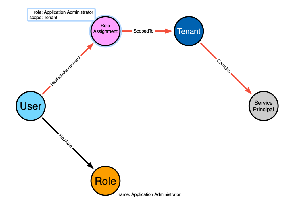
The highlighted path starts at the “User” node, follows directed edges, and ends at the “Service Principal” node. But this is not, in fact, a valid attack path. Why is that?
Stop and think about that question. What is it about our model that invalidates that as a valid attack path?
The fatal flaw of this model is that not all Entra admin roles contain abusable permissions.
“No problem”. You might think. “I’ll just exclude admin roles that don’t contain abusable permissions”.
Not so fast. One of the most powerful features of BloodHound is the per-object auditing it enables with its entity panels. For example, unrolling Active Directory security groups has been a cherished feature since the initial release in 2016:
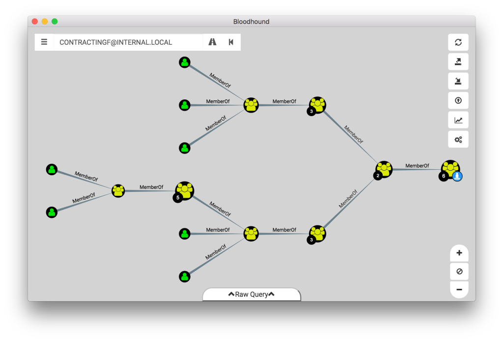
You can’t limit which roles users collect because users want to explore all roles, the same way we don’t limit Active Directory group collection.
How do we support collecting all this information while still producing valid attack paths? The answer is found in post-processing, traversable edges, and non-traversable edges.
A traversable edge is one that can be crossed during path finding – an open and safe road we can drive our car on.
A non-traversable edge is one that can not be crossed during path finding – a closed road we can’t drive our car on.
Let’s update our model to color-code our edges so we can distinguish the traversable and non-traversable edges. The traversable edges will be green, and the non-traversable edges will be red:
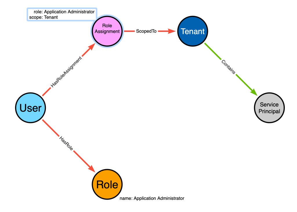
The only green edge is the “Contains” edge from the “Tenant” to the “Service Principal”. This edge is traversable because role assignments that are scoped to a tenant apply to all child objects of that tenant. I will explain that more as we continue to work with this model.
The above graph represents the configurations of the Entra system. Now we need to model the outcomes of this system. In other words, we are going to use the graph as a prediction system, where we are predicting the authorization decisions of the Entra system.
We will use post-processing to create a traversable edge connecting the “Bob” user node to the service principal. Post-processing is used for several things – here we will use it to encode our knowledge of the Entra authorization system mechanics into the graph.
Post-processing works by identifying patterns in the graph and adding new edges based on those patterns. It can be helpful to start your post-processing thinking with a statement about the modeled system. For example, we could make the following statement:
When a user in Entra has been granted the “Application Admin” role, scoped to the tenant, that user gains the ability to add new secrets to all service principals in the tenant.
Let’s go step-by-step through that statement and identify parts of the graph that match each part.
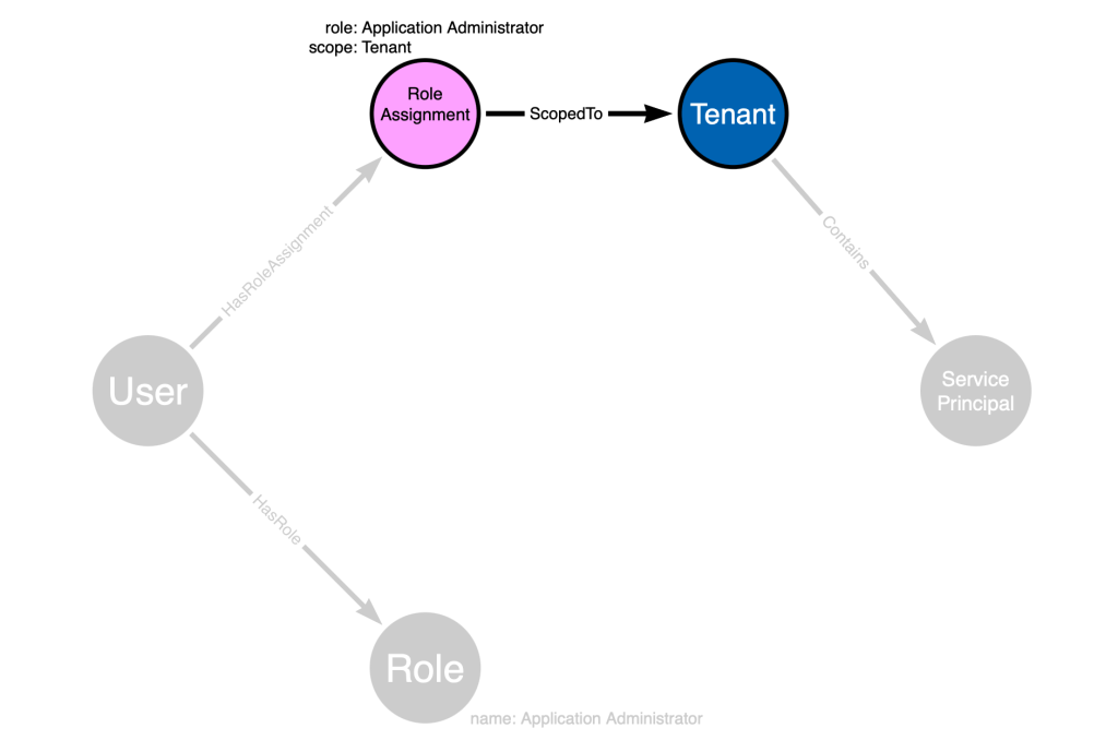
“When a user in Entra has been granted the ‘Application Admin’ role” matches this portion of the graph:
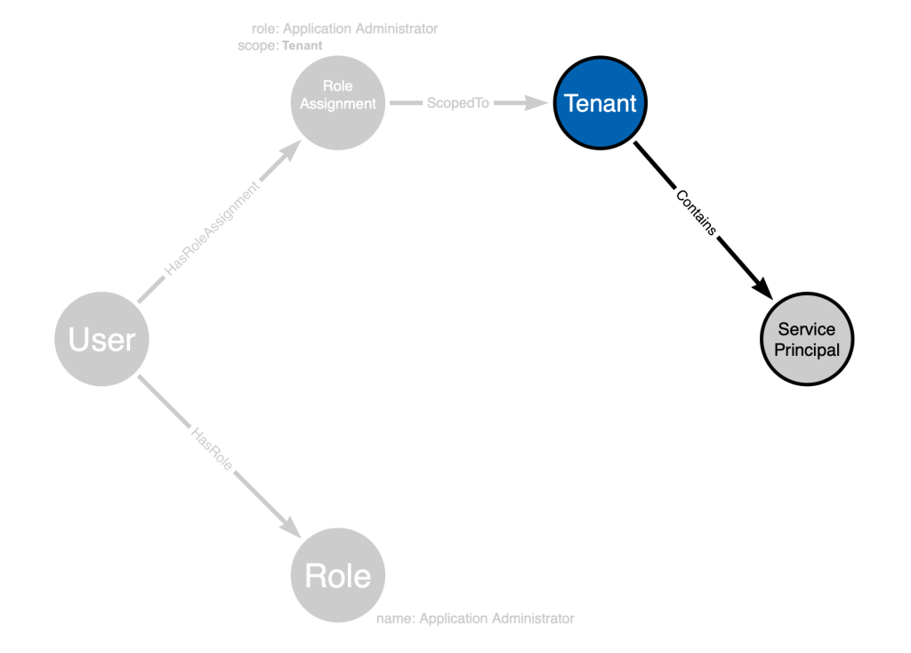
“scoped to the tenant” matches this part of the graph:
This part of the statement, “service principals in the tenant”, matches this part of our graph:
But what about this part of our statement: “the ability to add new secrets to all service principals”. We don’t have that in the model. So with post-processing, we will add a new edge to capture that part of the statement:
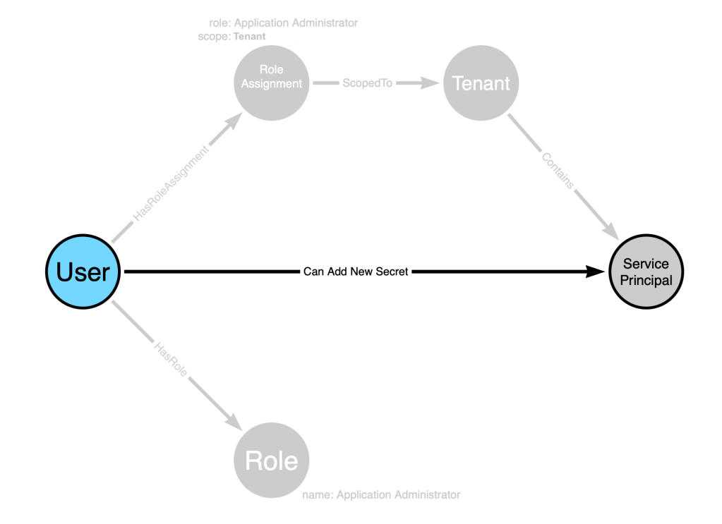
This edge added by post-processing will be traversable. Once post-processing is complete, our model now looks like this:
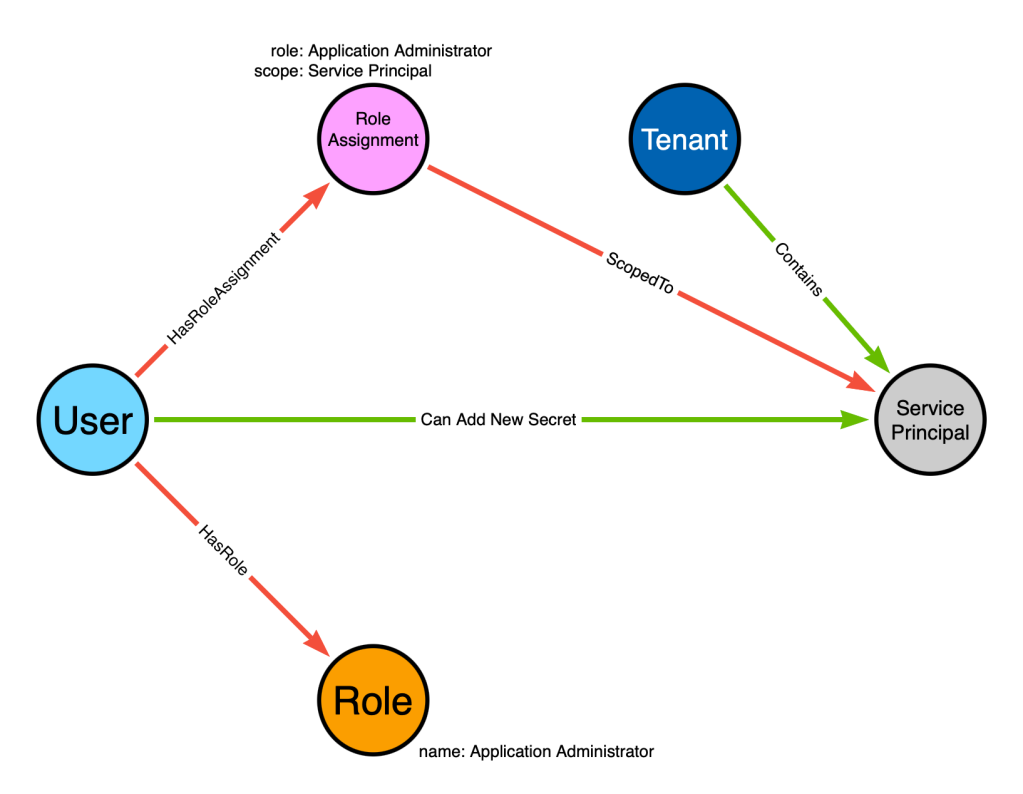
Let’s again color-code our traversable edges in green and non-traversable edges in red:

Now we can see that there is a traversable edge starting at the “Bob” user node and ending at the service principal node.
This model also works when the role assignment is scoped to the service principal, instead of the tenant:
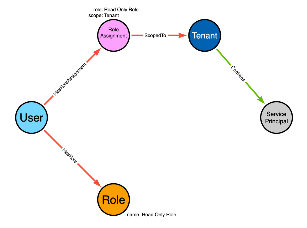
The model works when the role assignment isn’t abusable. We simply don’t create the traversable edge during post-processing:
You might be wondering: “What’s the point of the Role node?”
The “Role” node exists because users will want to search for them. Users want to search for Entra admin roles within BloodHound so they can explore:
- Who currently has this role assigned
- Who is eligible for this role via PIM
- The PIM settings for the role
Let’s check your knowledge with a quick quiz:
- True or false: when using Google maps to find a route to my destination, I love when it chooses routes full of closed, private, or otherwise impassable roads
- BloodHound’s pathfinding feature will only cross __________ edges
- What is the method called for enriching an existing graph with traversable edges that can’t be added at ingest time?
- Graph enrichment
- Post-processing
- Sending Rohan a DM on Slack and asking him to do it
- Depth-first search
- What are the two fundamental components of a graph?
- BloodHound attack graph edges are ___________, or “one-way”
Answers
- False
- Traversable
- Post-processing
- Nodes (or vertices) and edges (or relationships)
- Directed
Example 4: ADCS
Your attack graph design is dictated in-part by the availability and accessibility of different configurations. When data about a particular configuration is neither available nor accessible, you have the option to make informed assumptions.
For example, SharpHound can’t currently collect endpoint or network firewall rules. Yet we still include lateral movement primitives in the Active Directory model, even though an “AdminTo” or “CanRDP” edge might prove to be a “false positive” due to a firewall rule denying connections to the ports required by those primitives.
We made an informed assumption based on several years of experience across hundreds of corporate LANs that these abuse primitives would remain reliable due to a general lack of internal network segregation.
We made a similar informed assumption in our Active Directory DACL-based abuse primitive model when we chose to not include DENY type ACEs. Our experience across hundreds of Active Directory environments was that DENY ACEs are exceedingly rare in the real world.
ADCS presented a unique challenge to us when it came to modeling ADCS attack paths in the graph. The two major characteristics of that challenge were:
- Each named ADCS abuse primitive relied on connections and configurations across several disparate Active Directory objects
- The data necessary to make accurate predictions of whether those abuse primitives would emerge in any given AD deployment was available and accessible.
In this instance, we did not need to make any assumptions, informed or otherwise. We could predict, with a high degree of certainty, that our model would accurately predict the emergence of several of the named ADCS abuse primitives.
The best example of how we did this is ADCS ESC1.
At x33fcon 2024, Jonas Bülow Knudsen and I presented on how exactly we model ESC1 in the BloodHound graph. You can see that part of our presentation here:
There are several elements that must align in order for ESC1 to emerge. These are the original elements documented in the “Certified Pre-Owned” whitepaper:
- The Enterprise CA grants low-privileged users enrollment rights.
- Manager approval is disabled.
- No authorized signatures are required.
- An overly permissive certificate template security descriptor grants certificate
enrollment rights to low-privileged users. - The certificate template defines EKUs that enable authentication.
- The certificate template allows requesters to specify a subjectAltName in the CSR.
Disclaimer: The following portion of this document illustrates the logic of the ADCS model, but is not wholly representative nor completely accurate to the production model. This content is meant to educate through illustration, not replace a constantly up-to-date technical reference.
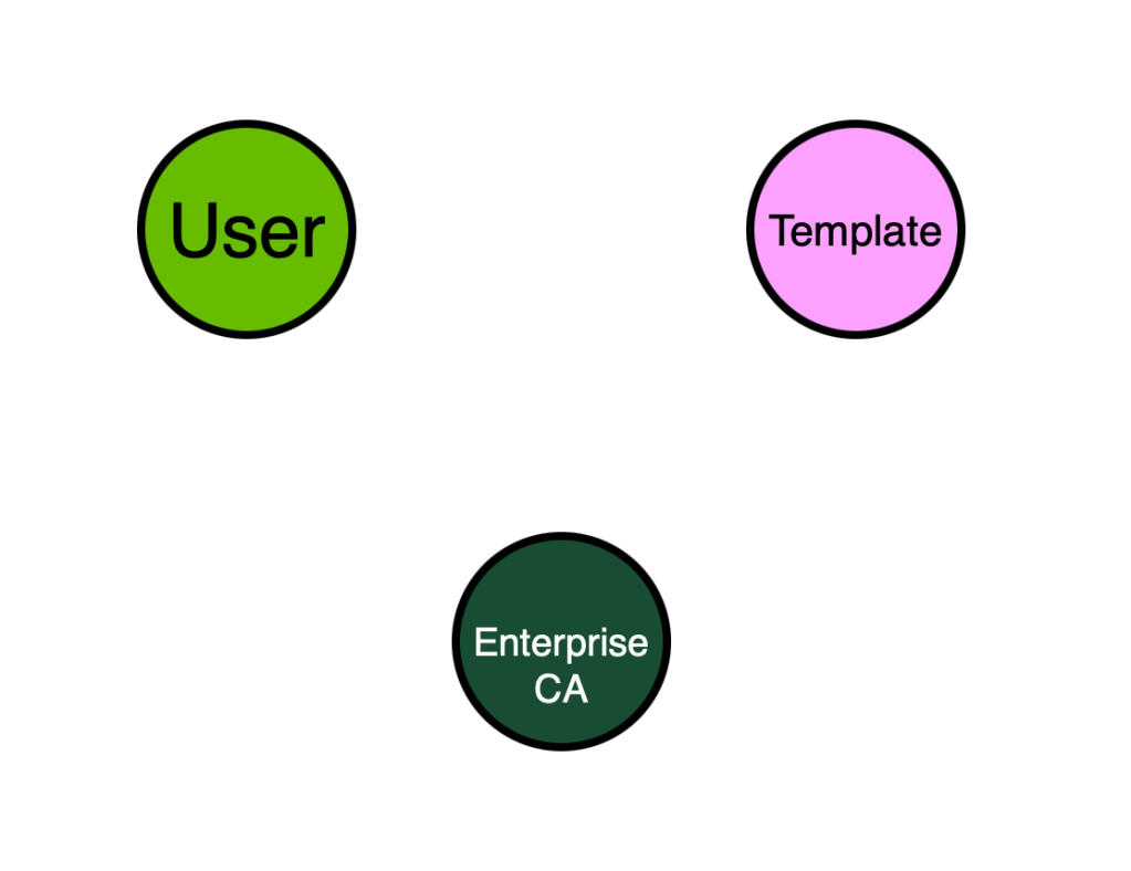
Let’s do our best to build a model from these requirements and see how far we can get. We can identify the following node types from the requirements:
- User
- Enterprise CA
- Template
What edge types can we use to start connecting these nodes? From the above requirements we can identify the following statements that will help us:
- “The Enterprise CA grants low-privileged users enrollment rights.”
- “An overly permissive certificate template security descriptor grants certificate
enrollment rights to low-privileged users”
Let’s not worry too much about the finer details and just start off with some basic “EnrollRights” edges. These will be placeholders for now:
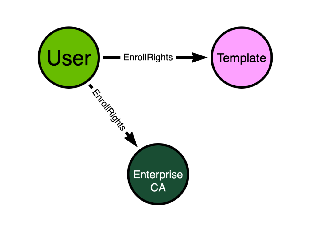
What about the other configuration details we didn’t capture yet? Those include:
- “Manager approval is disabled.”
- “No authorized signatures are required.”
- “The certificate template defines EKUs that enable authentication.”
- “The certificate template allows requesters to specify a subjectAltName in the CSR.”
Let’s add those configurations as node properties in our model:
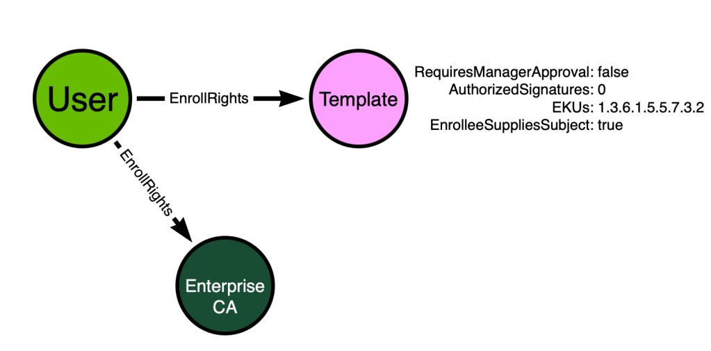
Is this model “good enough”? We can check by remembering one of the requirements for BloodHound attack graphs:
Your Model Must Connect Non-Adjacent Nodes with Paths
There are paths in the above model starting from the “User” node and ending at the “Template” and “Enterprise CA” nodes. But those nodes are all adjacent – directly connected by an edge. But because there are no paths connecting non-adjacent nodes, this model will not suffice.
In order to proceed, we must understand what the outcome of ESC1 is. The outcome of ESC1 is that a principal gains the ability to impersonate any other user in an Active Directory forest. In order to model that outcome in our graph, we have two options:
- Create a post-processed edge from the “User” node to every other “User” node in the AD forest
This option is not attractive as it will result in the creation of hundreds, thousands, even millions of new edges in the database. Which leads us to option 2:
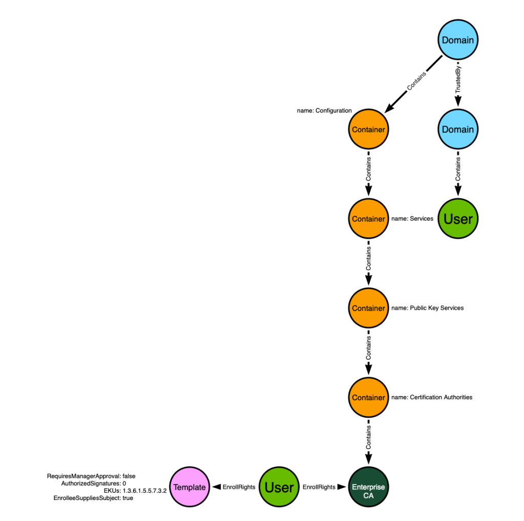
- Create a post-processed edge from the “User” node to the forest root domain object
This option is attractive because it results in the creation of only one post-processed edge and takes advantage of the existing data model that includes Active Directory domains, their trust relationships, and their descendent users. Let’s add the existing model to our proposed model:

We have a lot of the necessary information now in the model to predict the emergence of ESC1, but we are missing some crucial components that may not be obvious if you haven’t read the ADCS whitepaper. ESC1 only emerges when all of the following elements, not yet captured by our model, are true:
- The involved Enterprise CA is trusted as a Root CA by the target Active Directory forest, OR the involved Enterprise CA chains up to a Root CA
- The involved Enterprise CA is trusted to perform NT authentication for the target AD forest
- The involved certificate template is published to the involved Enterprise CA
It’s not safe to assume that every CA in every AD forest around the world will always meet those first two requirements. It’s not safe to assume that every certificate template in every AD forest around the world is published to every CA.
Those assumptions are not safe to make, and we do not need to make those assumptions, either. All of the information in those three requirements is easily accessible via LDAP by a low privilege principal:
- Trusted root CAs are stored in the “Certification Authorities” container in the “Configuration” naming context. CA chains are readable by parsing the certificates themselves which are, again, readable in LDAP.
- CAs that are trusted for NT authentication are referenced by the NTAuthStore object in LDAP.
- CAs list which templates are published to them – and that information is accessible via LDAP.
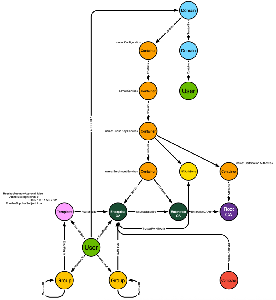
We know that we can identify root CAs by their location in the LDAP hierarchy, so let’s add that to our model:
We can also add the NTAuthStore object in its proper place within the hierarchy and model the fact that the NTAuthStore references the Enterprise CA:
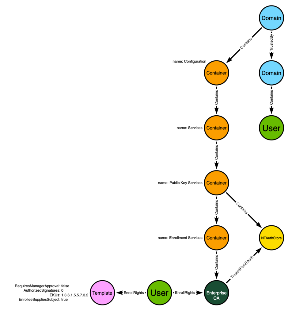
Next, we can model the fact that the Template is published to the Enterprise CA:
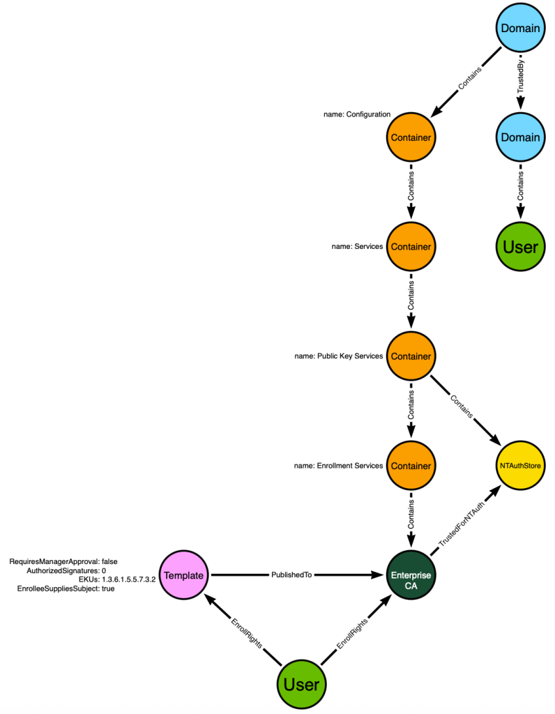
The model now includes all the information needed to predict that the “User” at the bottom of the graph will be able to impersonate the “User” in the top right part of the graph.
But this model still falls short because it doesn’t incorporate common configurations that real-world admins use. In this case specifically the model is not taking the following into account:
- Users sometimes have direct access to objects as shown in the model with the “EnrollRights” edge from the “User” to the “Template” and “Enterprise CA” nodes; however, it is much more common that groups are the principal type referenced on an ACE. This model does not allow for the “User” node’s “Enroll” access being granted through security group delegation.
- Admins often deploy multi-tier PKI hierarchies, where there is an offline root CA, online intermediate CAs, and online issuing CAs. The above model does not allow for this, instead assuming that every PKI deployment in the world will be as simple as what is shown in the above graph.
For those reasons, this model will fail to accurately predict the emergence of ESC1 in the real world. Thankfully, we can improve the model to close the gap.
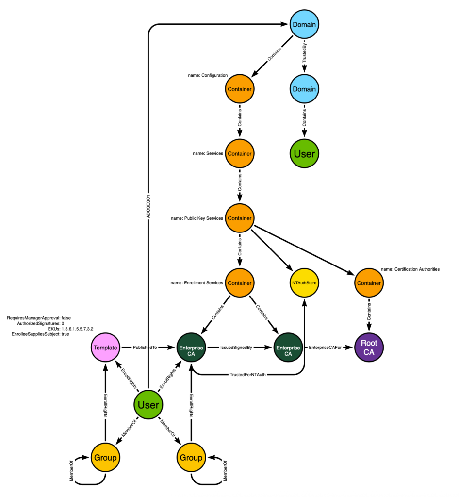
First we will extend the model to allow for principals to gain enroll rights through security group delegation:
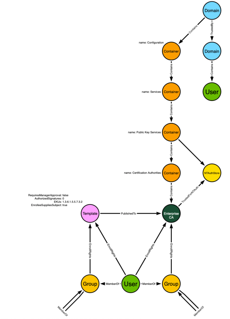
Don’t forget that groups can be nested into groups. That is what the “MemberOf” edges starting and ending at a “Group” node indicate – that these users can gain privileges through any number of nested security group memberships.
Next we will account for multi-tier PKI hierarchies by modeling the “Enrollment Services” container and the CAs that reside in that container. This is where AD stores information about CAs where those CAs are expected to be online and available for enrollment activities:
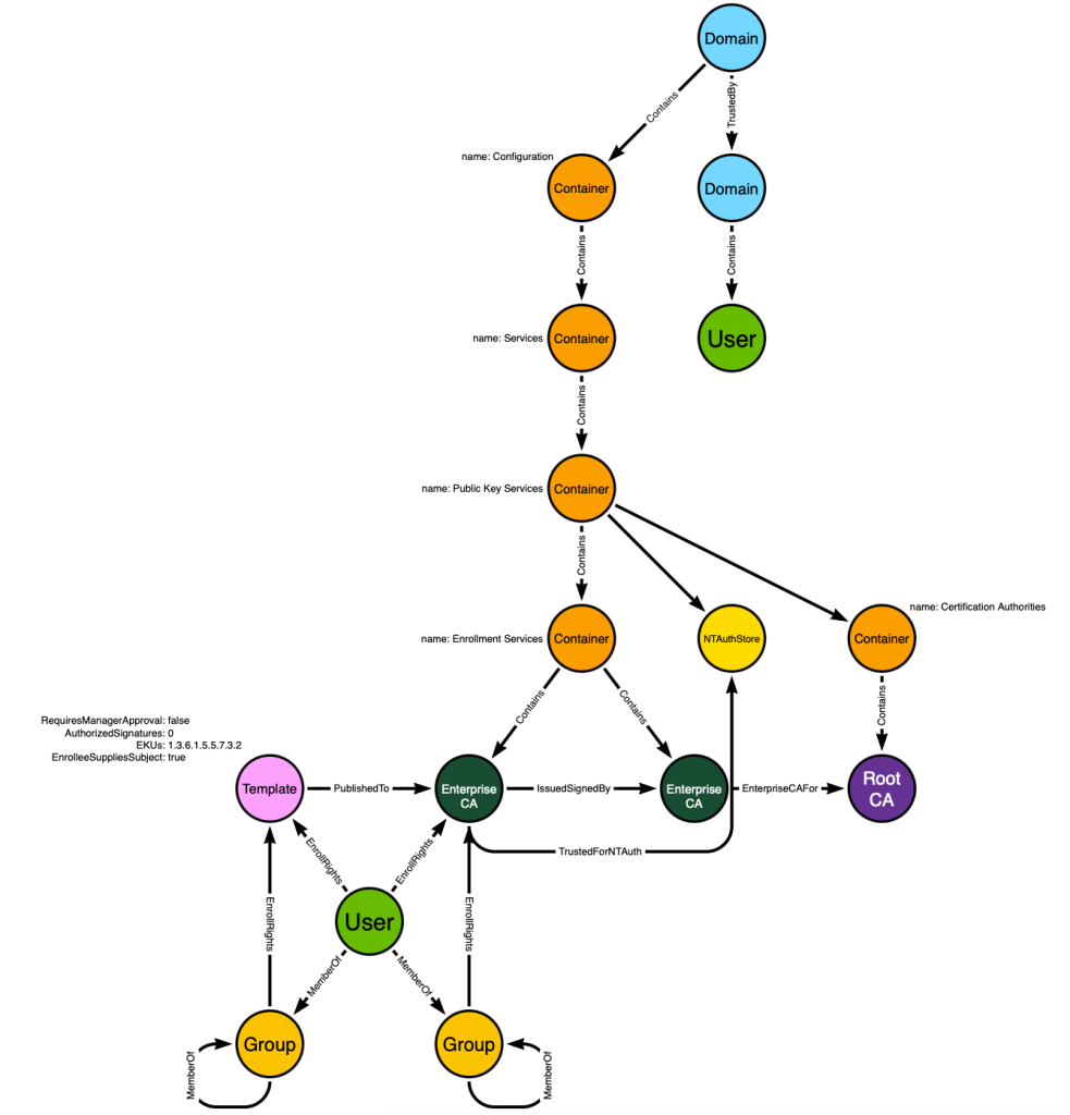
This model is now capable of accurately predicting the emergence of ESC1 based on our understanding of the system mechanics and likely real-world configurations. It includes all of the information needed in order to identify not just the one “User” towards the bottom with ESC1 ability, but more importantly it is capable of identifying all principals in all Active Directory forests with ESC1 ability.
There are still some assumptions this model makes that could result in a wrong prediction (aka false positive):
- There could be a “DENY” type ACE that results in the principal not actually being able to enroll in a template
- There could be endpoint firewall rules that block the traffic necessary to request enrollment in different templates
- The host represented by the LDAP object is offline
But remember from earlier we discussed the difference between what is possible and what is common. A three-tier PKI hierarchy is both possible and common, and therefore the model must take that into account. A “DENY” type ACE is possible but uncommon, and therefore the model does not need to take those into account.
Determining which characteristics of a system are common and uncommon should not be taken lightly. It should not be based on vibes. It should be based on careful examination and study of real-world environments to the best of your ability.
Let’s wrap this example up by seeing how post-processing completes the picture. From the above model, we can execute the following cypher query that takes all known and possible system mechanics and configurations into account in order to predict the emergence of ESC1:
MATCH (d:Domain {objectid:'S-1-5-21-1004336348-1177238915-682003330'})
MATCH (rca:RootCA)-[:RootCAFor]->(d)
MATCH (ca:EnterpriseCA)-[:IssuedSignedBy|EnterpriseCAFor*1..]->(rca)
MATCH (ca)-[:TrustedForNTAuth]->(nt:NTAuthStore)-[:NTAuthStoreFor]->(d)
MATCH (ct:CertTemplate)-[:PublishedTo]->(ca)
WHERE (ct.requiresmanagerapproval = false
AND ct.schemaversion > 1
AND ct.authorizedsignatures = 0
AND ct.authenticationenabled = true)
OR (ct.requiresmanagerapproval = false
AND ct.schemaversion = 1
AND ct.authenticationenabled = true)
OPTIONAL MATCH (n)-[:GenericAll|Enroll|AllExtendedRights]->(ct)
OPTIONAL MATCH (m)-[:MemberOf*1..]->(n)
WITH ca,COLLECT(n) + COLLECT(m) AS CTEnrollers,d
OPTIONAL MATCH (o)-[:Enroll]->(ca)
WHERE o IN CTEnrollers
OPTIONAL MATCH (q)-[:MemberOf*1..]->(:Group)-[:Enroll]->(ca)
WHERE q IN CTEnrollers
WITH COLLECT(q) + COLLECT(o) + CTEnrollers AS CTandCAEnrollers,d
MERGE (CTandCAEnrollers)-[:ADCSESC1]->(d)
Dislaimer: The above query does not necessarily represent the actual production logic of BloodHound. This is for educational purposes and is not meant to serve as permanently up-to-date documentation.
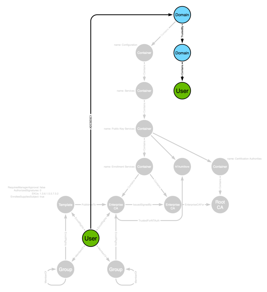
I will save the in-depth cypher lesson for another time. The end result of this query is the creation of a post-processed, traversable edge of the ADCSESC1 class. The edge starts at the principal with ESC1 ability and ends at the forest root domain node:

Now when we run a pathfinding algorithm starting at the bottom user and targeting the upper user, we will discover this path:
Or we can lay this out and remove the noise to see a simpler view:
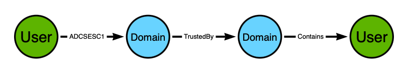
The path starts with the “User” on the left and ends with the “User” on the right. The user on the left can perform ESC1 to impersonate the user on the right.
This is the view we can expect a BloodHound user to see in the BloodHound GUI when this path is found. But we’ve now created a new problem: there isn’t enough information to understand why the user on the left can performed ESC1. By condensing all of the other node/edge information into this simple post-processed edge (ADCSESC1), we have obscured the necessary details that both an adversary and a defender need in order to do their jobs:
- The adversary has no idea from this view alone which template and CA to target when attempting to impersonate the target user
- The defender has no idea from this view how to remediate the issue and remove a potentially dangerous attack path from their environment
That brings us to our next concept: composition edges.
Composition edges are constructed edges that rely on the existence of one or more other edges, and may also represent node properties. They are created by post-processing. They are often traversable, but not required to be.
Composition edges are the solution to the above problem, where a singular edge and the nodes it connects do not contain enough information for an adversary or defender to take action. In the BloodHound GUI, composition edge entity panels get an additional accordion item called “Composition”.
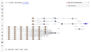
When the BloodHound user clicks the “Composition” accordion, the application displays all of the nodes and edges that were taken into account when constructing the composition edge:
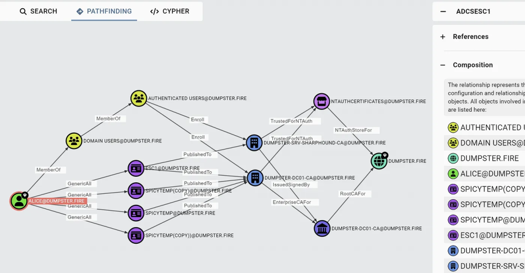
The above screenshot is from this blog post: ADCS Attack Paths in BloodHound — Part 1
The “composition” layout above tells the BloodHound user:
- The eligible templates that are susceptible to ESC1
- The target CAs the those templates are published to
- The patterns connecting those CAs to the domain head through root CA and NTAuthCerts
- The AD forest root domain that the user can perform ESC1 against
All of that information is what either an adversary or defender needs in order to exercise or remediate the attack path.
Example 5: GoldenCert
The previous example showed how to model a complex system like ADCS with a similarly complex abuse primitive in ESC1. In this example we will build on the ADCS model to present paths that emerge from a more simple abuse primitive known as “Golden Certificate”.
The foundation of trust in ADCS from which all capabilities emerge is a private certificate. That private certificate is used to sign other certificates. For example, the private certificate may be used to issue a certificate for an online certificate enrollment service.
If an adversary can read the private certificate of an ADCS CA that is…
- Trusted as or chains up to a CA trusted as a root CA by Active Directory
- Trusted for NT authentication by Active Directory
…then that adversary can mint their own certificates that will be trusted by the entire AD forest for the purposes of authenticating as any principal; hence: “Golden Certificate”.
Here is the ADCS data model as we left it in example 4:
Keep in mind that we are interested in an adversary gaining access to the private certificate itself. Here’s why the current model will not suffice when mapping the Golden Cert attack path:
- The “Enterprise CA” and “Root CA” node types represent LDAP objects. Those LDAP objects do not store the private certificate.
- Control of any of the objects seen does not guarantee access to the private certificate. You can have “Generic All” (full control) of the “Root CA” node, but that doesn’t give you access to the private certificate
We need to think about the ADCS system and service itself. The ADCS enrollment service will reside on a host. The private certificate will be stored on the host, as the ADCS service needs to use the private certificate to perform signing tasks.
We know the private certificate will be available to the ADCS service host, so we will introduce a :Computer labeled node to the graph design:
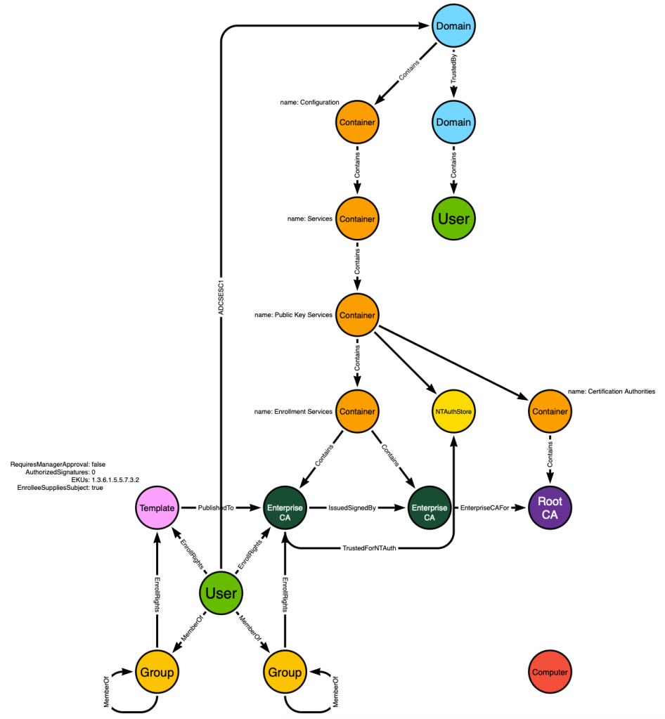
We also know that during certificate enrollment, the ADCS client (a user or computer) will find the ADCS enrollment server by reading the “Enterprise CA” LDAP object to find a hostname. It will resolve that hostname via DNS to identify the host where the ADCS enrollment service is hosted.
We can mimic this behavior to identify the :Computer node hosting each :EnterpriseCA service. That will allow us to create a post-processed edge starting from the :Computer and ending at the :EnterpriseCA node. The edge will be called HostsCAService:
Now we can create an additional post-processed edge starting at the :Computer node and ending at the :Domain node. The edge class will be GoldenCert:
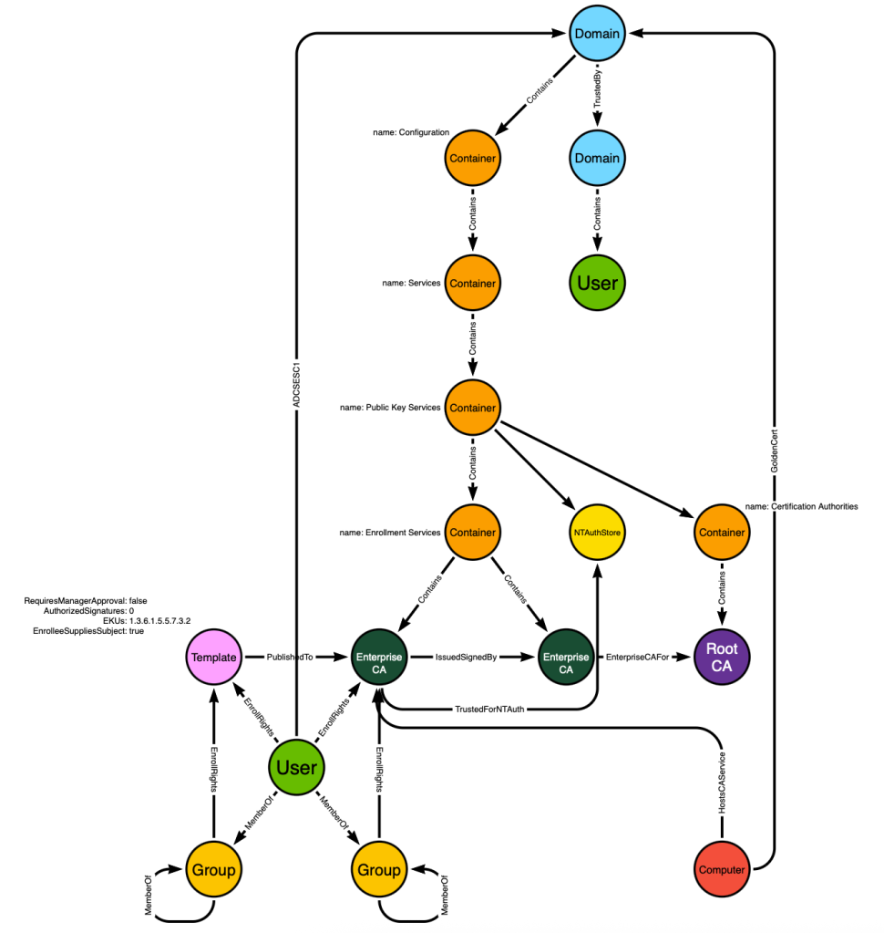
We’ve now made the :Computer and :Domain nodes adjacent. But remember that the :Computer nodes in BloodHound have other inbound edge classes against them, like AdminTo for example. That means we are able to present attack paths that traverse the “GoldenCert” edge where those paths require an adversary to first compromise the computer hosting the ADCS service:
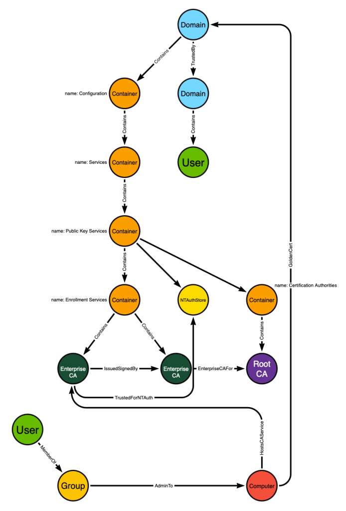
The user in the lower right is a member of a group which has admin rights on the computer. That computer has access to the private key used by an ADCS service that is trusted as a root CA and for NT authentication. Compromise the computer → compromise the private key → compromise the domain.